Cybersecurity from the offensive perspective is not only related to web-applications and Active directory attacks. There are a lot of hacking areas beside mentioned ones: mobile, API, operational technology (OT), and wireless attack simulations; binary exploitation, social engineering, red teaming and many more other. One of the toughest one, from my point of view, is hardware hacking, when you are communicating directly with the layer 1 of OSI model – physical. If you are excited as much as I am to disassemble some devices – let’s not waste any second and dig into learning together 😉
0. Definition
So, what is the hardware hacking actually? Hardware hacking is the process of modifying or manipulating the physical components of electronic devices, such as computers, smartphones, routers, or any other hardware, to achieve purposes beyond their original design. This can involve various activities such as soldering, rewiring, reverse engineering, or adding new functionality to the hardware as well as tampering with devices to steal information, bypassing security measures for unauthorized access, or creating counterfeit products.
Hardware hacking can be done for various reasons, including:
- customization – modify hardware to personalize it according to their specific needs or preferences
- enhancement – improving the performance or capabilities of a device, such as overclocking a processor or adding more memory
- security testing – hack hardware to identify vulnerabilities and weaknesses that could be exploited by malicious actors
- education and experimentation – learn about electronics, programming, and cybersecurity through hands-on experimentation
- prototyping – prototyping and development to create proof-of-concept designs or to modify existing hardware for new applications.
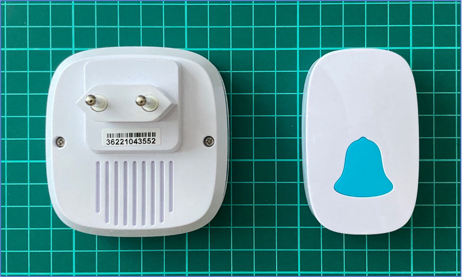
1. The wireless doorbell
As many of you may remember, in August 2023 we issued an article / book regarding hacking radio waves called “HackRF as the best SDR friend for hackers” (https://www.ivanglinkin.com/hackrf-as-the-best-sdr-friend-for-hackers/). In chapter 7 we discussed together about the Sky-Touch Wireless Doorbell (FCC 214-104757): we intercepted the radio signal from the remote, extracted the payload, synthesized the signal and sent it back to the doorbell making it worked.
During the analysis phase we inspected the radio signal, performed the demodulation and extracted the actual payload which was 1000111011101000100011101110100011101000100011101000100010001110100010001110100010001000100011101(000).

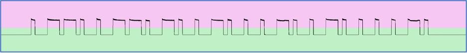
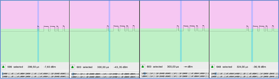
As you can see each part of the signal consists of peaks (1 – ones) and rest (0 – zeros). But, if we look closer, we can find the pattern which is 1000 or 1110 in different sequence. Because they are repeated, we can represent 1000 as 0 and 1110 as 1. In that case, our final signal is going to be 0110011010010001001000010. Let’s remember that number.

Another 2 items we want you to look at are number of elements selected and duration which are 1285 and 1,28 ms respectively. Actually, we don’t need them for hardware hacking, but we will use them for comparison perspective.
2. Disassembling
To perform hardware hacking first we need to disassemble the box. In our case we even don’t need to use a screwdriver as the remote doesn’t have any screws at all.
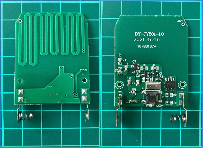
What can we see here? As you can mention, there are contacts for a battery followed by button to link the chain with a LED indicator next to it.
Next, the heart of the transmitter – the SAW (Surface Acoustic Wave) Resonator LR433T2. It is needed for frequency filtering and selection the 433MHz frequency range. The LR433T2 works by converting electrical signals into surface acoustic waves that propagate along a piezoelectric substrate. These waves undergo constructive interference at 433MHz, creating a resonant effect, allowing the LR433T2 to pass signals at its resonant frequency.
Next to it is a chip JY 501B 2142 the main purpose of which is to generate the payload. Next, there are 3 transistors combined with capacitors and resistors to amplify the signal.
The last item is antenna which is made in a Printed Circuit Board trace.
Unfortunately, we were not able to find the circuit diagram for this remote. If you have some free time, you can draw it as it’s quite simple and easy to duplicate. But for our current purposes the simplify circuit is more than enough.
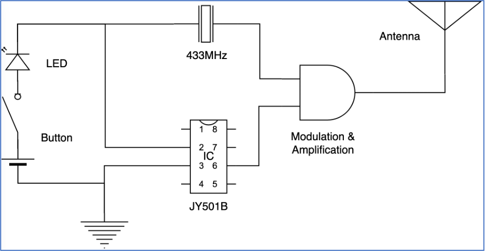
As you can see in the scheme, we have the SAW Resonator LR433T2 which is generating 433,92 MHz frequency signal and JY501B which is generating the payload. They are meeting in the middle for modulation and amplification purposes and then going to the antenna.
So, our target is to get the signal from the chip. Let’s do it.
3. Finding the pin
We know this is a low budget project and we don’t expect the signal is going through several microchip’s pins. Most probably there is only one specific pin and we have to find it. Unfortunately, we did not find the datasheet for JY501B chip across the whole internet so the exercise is more challenging right now: no circuit diagram, no datasheet 🙂 Completely reverse engineering without any help.
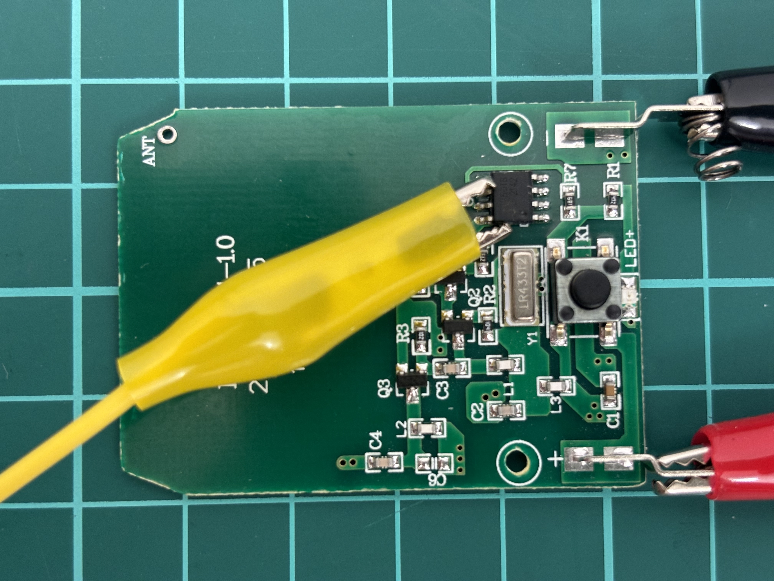
To find the right pin on the chip as well as performing hardware hacking at all we need an equipment. For this exercise we are using the next:
- Raspberry Pi 4B
- breadboard
- some jumpers and crocodile connectors
- LED with a resistor
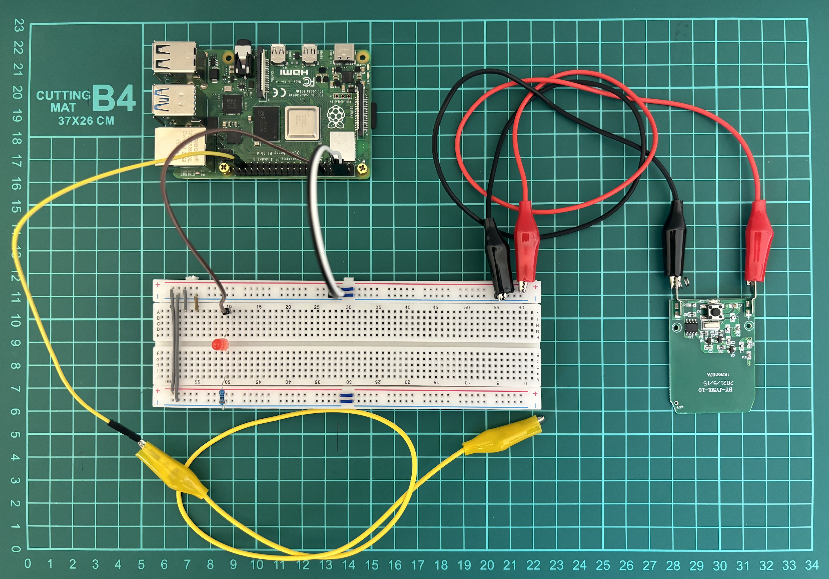
Let me explain what is going on here.
- Pins 4 (5V) and 6 (GND) from Raspberry Pi are connected to the “+” and “-“ on the breadboard using white and black jumpers respectively;
- Pin 12 (GPIO18) through the brown jumper is connected to LED, followed by resistor and finally connected to the “-“ / GND. This Pin 12 (GPIO18) is set up as OUTPUT means when it’s active, the LED lights;
- Pin 37 (GPIO26) through the yellow jumper is set up as INPUT means we will get data from this particular wire. Basically, we have a jumper first with a sharp needle to temporary connect to the chip, followed by crocodile jumper to connect solidly;
- Through the red and black crocodile jumpers we powered the remote. Originally, the remote has 12V battery, but we give him 5V.
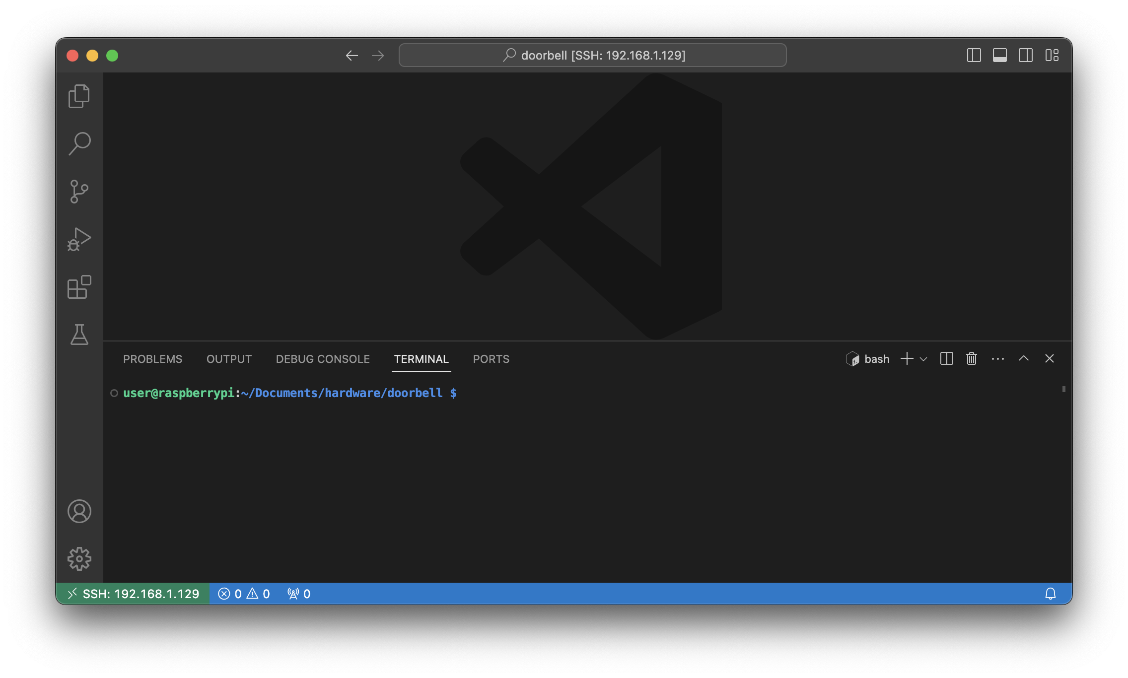
As a software we use Visual Studio Code with “Remote – SSH” extension.
It’s a little bit inconvenient to work from Raspberry with a connected keyboard, mouse, screen and power supply so it’s tough to manipulate jumpers. To minimize that, we connect from our Visual Studio code, installed on the main PC, through the “Remote – SSH” extension to the Raspberry. In that case we are working using our suitable environment with the technical stuff. Also, in case we would make a mistake and connect something wrong hence our stuff burned down, our main PC is in save.
Ok, we set everything right and can start our hacking.
The first and the main thing we have to do, as we already mentioned above, is to find the right pin – the pin from which the payload is going out. Let’s write a small Python code to visually find that one.
import RPi.GPIO as GPIO
# Set up GPIO using BCM numbering
GPIO.setmode(GPIO.BCM)
# Define the pin numbers
input_pin = 26
output_pin = 18
# Set up the pin as input
GPIO.setup(input_pin, GPIO.IN)
GPIO.setup(output_pin, GPIO.OUT)
while True:
# Read the value of the input pin
pin_value = GPIO.input(input_pin)
# Check if the pin value is 1
if pin_value == 1:
GPIO.output(output_pin, GPIO.HIGH)
else:
GPIO.output(output_pin, GPIO.LOW)
The main idea of the code is, basically, when we get a signal to GPIO26 pin (yellow wire) – the LED is on, if there is no signal – the LED is off.
So, let’s press the button on the remote and start checking chip’s pin by pin using our jumper’s needle.
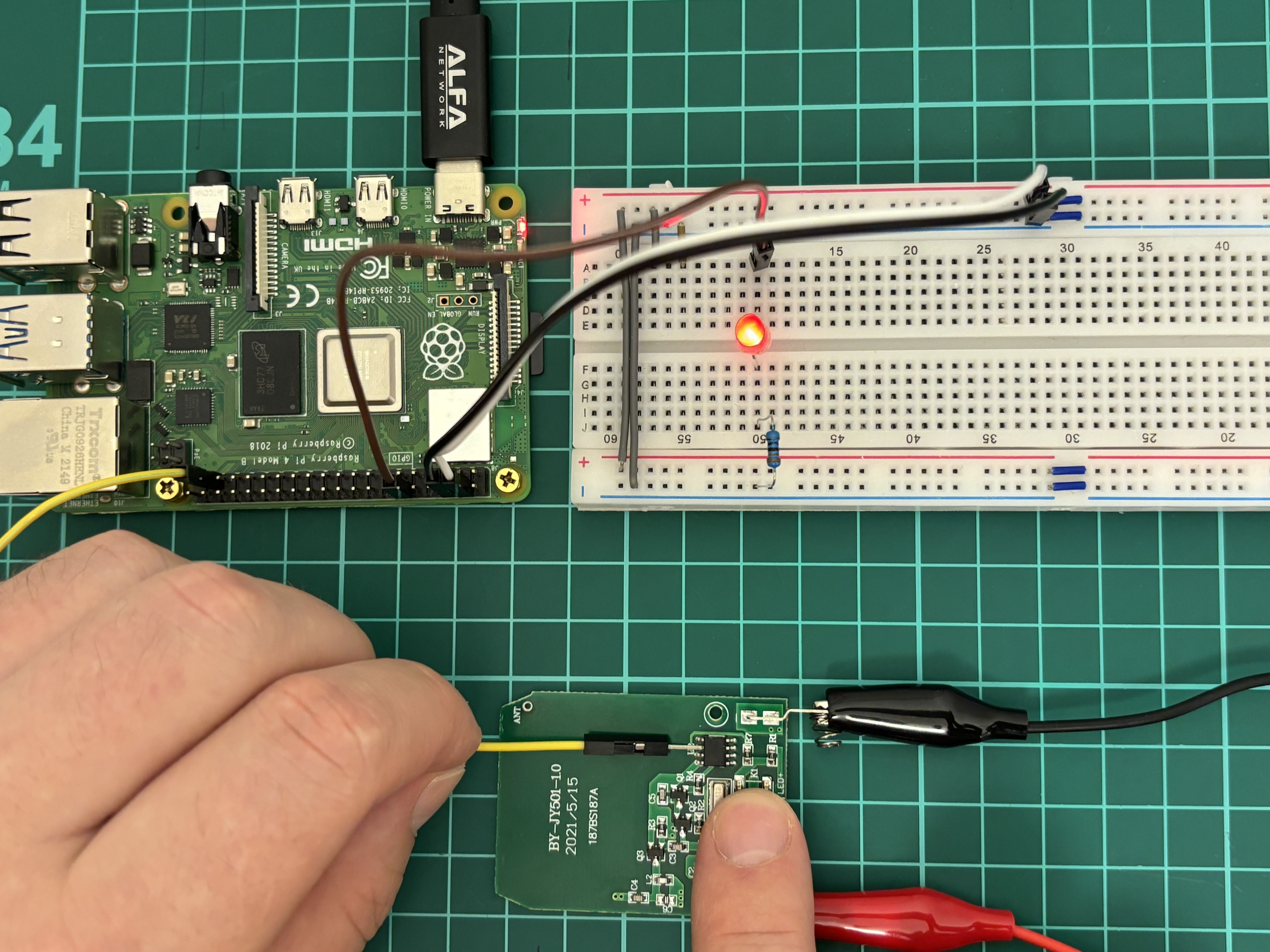
So, we are starting from the pin # 1, which is next to the hole and going counterclockwise. When we connect to the pin # 1 the LED is On. Pins 2, 3, 4 and 5 are the same – the LED is On.
When we connect to pin # 6 – the LED is blinking, not evenly, but seems like with a pattern. Hm… I guess we have found that, but let’s check the rest ones.
Pin # 7 – LED is On, pin # 8 – LED is Off.
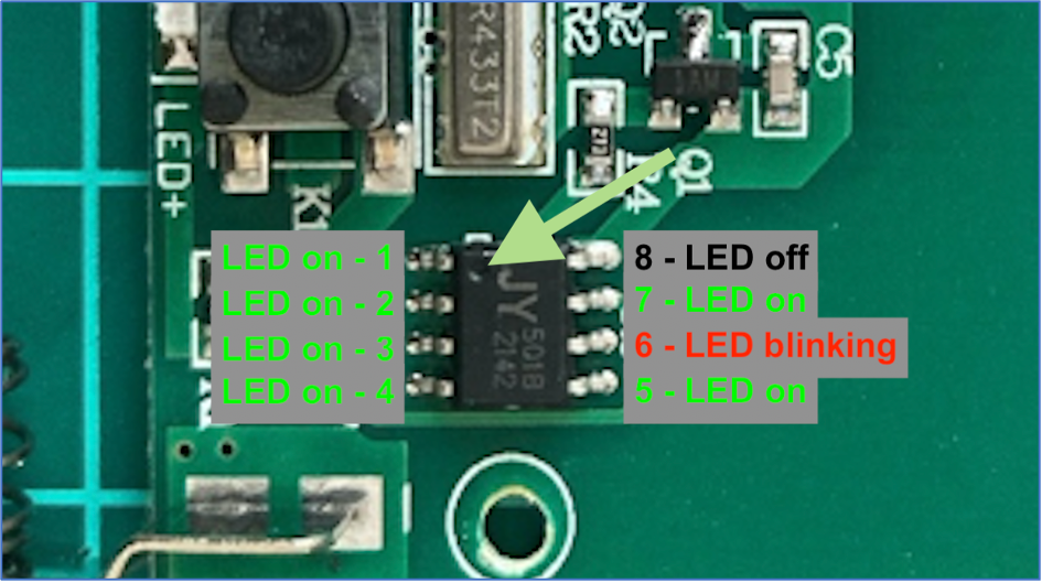
Ok, we have 3 statuses: LED On – pins 1, 2, 3, 4, 5, 7; LED Off – pin 8; LED blinking – pin 6. Definitely, pin # 6 is our target right now.
4. Getting the pattern
Having found the right pin, let’s proceed analyzing. First, we will add the additional jumper – the crocodile one, to the yellow wire. We need that jumper so we can have a solid contact with the chip.
But please be careful so your crocodile is not touching other contacts. The least what can happen – your code just won’t work. But in the worst-case scenario – you may burn down the device.
If everything is done correctly, let’s rewrite our code and get the output to the screen.
import RPi.GPIO as GPIO
# Set up GPIO using BCM numbering
GPIO.setmode(GPIO.BCM)
# Define the pin numbers
input_pin = 26
# Set up the pin as input
GPIO.setup(input_pin, GPIO.IN)
while True:
# Read the value of the input pin
pin_value = GPIO.input(input_pin)
# Check if the pin value is 1
if pin_value == 1:
print(“1″, end=””)
else:
print(“0″, end=””)
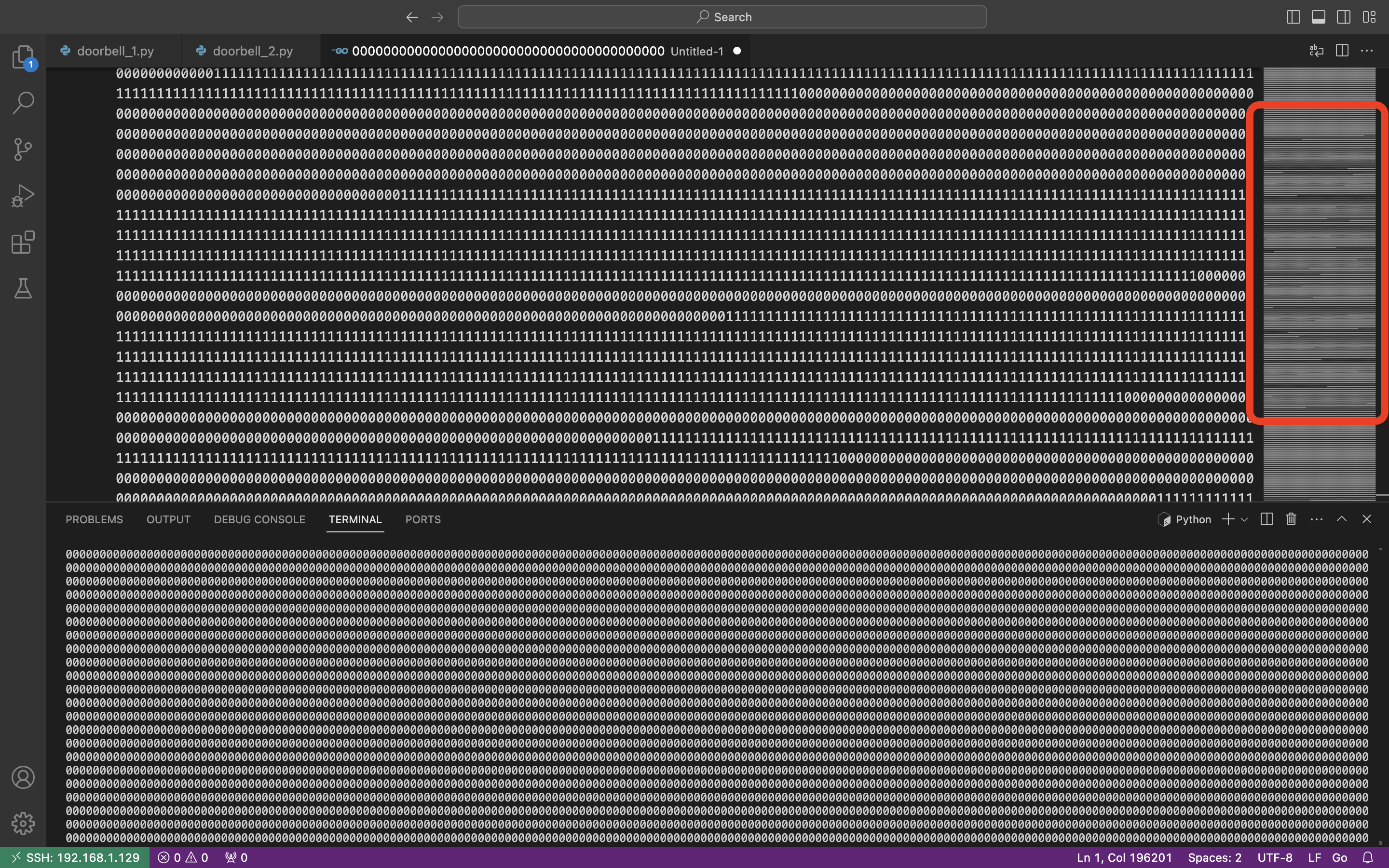
We removed the LED indication from the code so we can fully focus on the signal. So, let’s run the code and press the ring button on the remote.
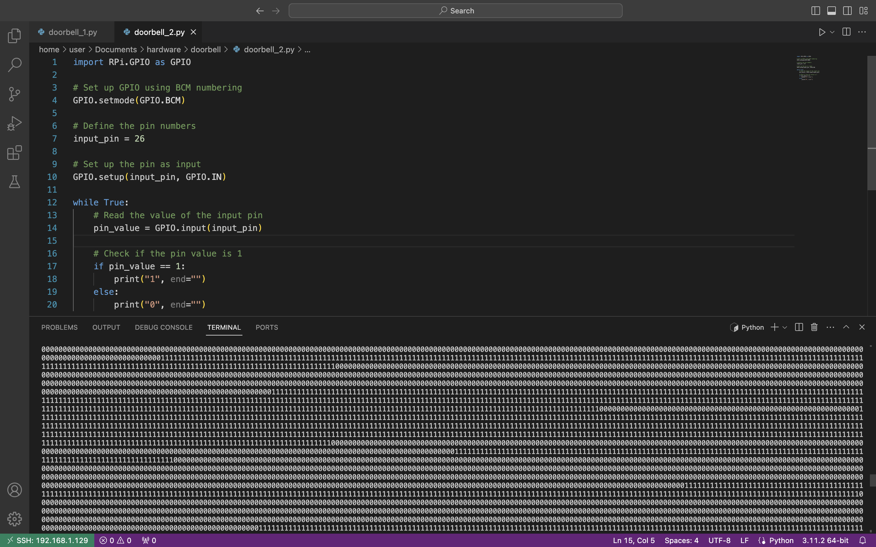
Wow, it works. We can see “0” if there is no voltage and “1” when we have it. And the duration of each section is different which is fully aligned with our visual observation – the LED lighted not evenly. We would suggest to copy the output as a dedicated text file and try to analyze it manually first.
Wow, look at the code preview on the right side of the picture. Does not that seem familiar? We have already seen that in the current article.
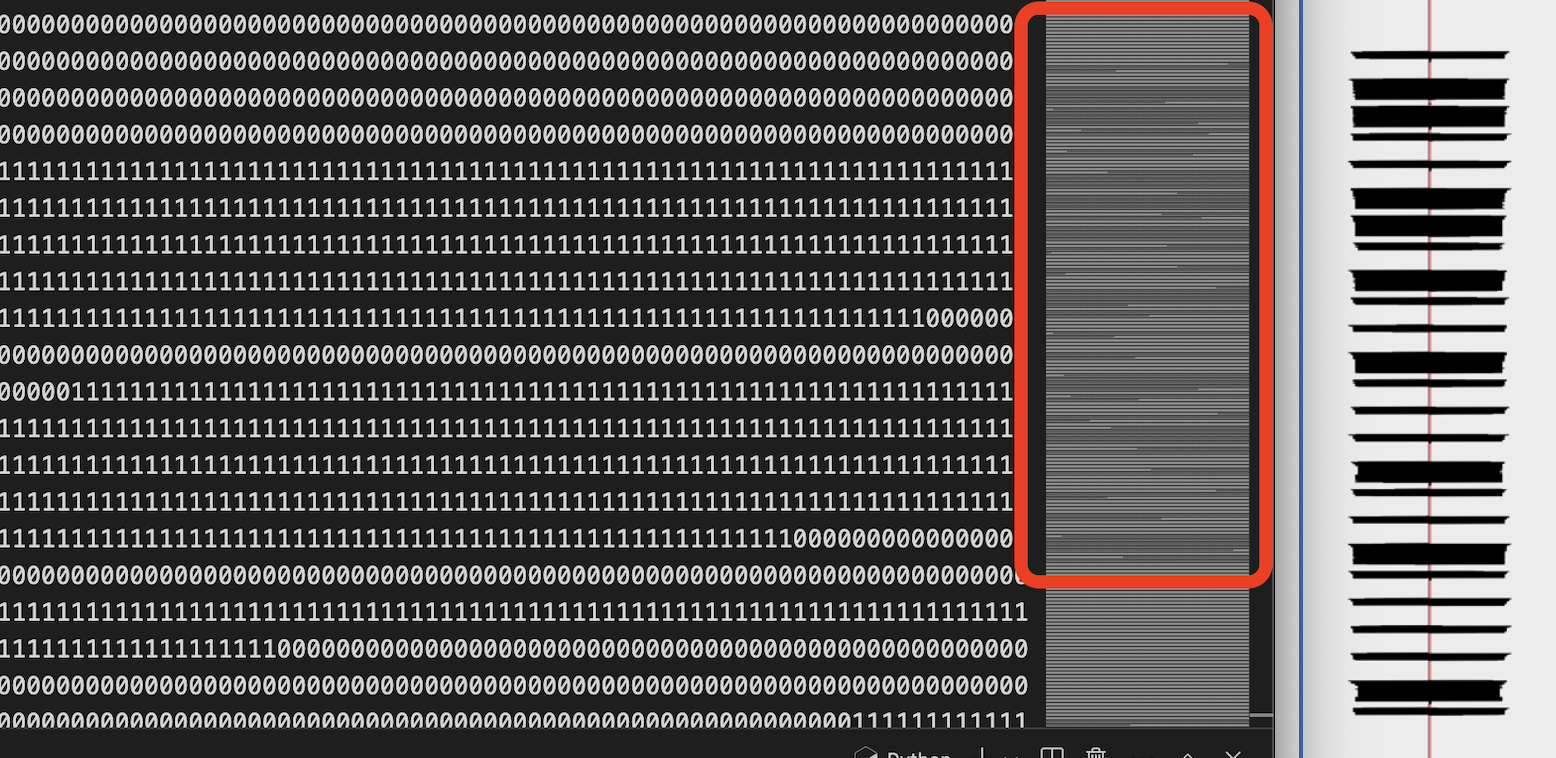
Amazing, the code preview is fully aligned with the radio wave signal harvested before. Do you know what does that mean? It means we are doing everything correctly 🙂
5. Automatization
Great, we know that are on the right path. And the next step is to automatize it.
Let’s write another code to calculate the payload once we receive it.
import RPi.GPIO as GPIO
# Set up GPIO using BCM numbering
GPIO.setmode(GPIO.BCM)
# Define the pin numbers
input_pin = 26
# Set up the pin as input
GPIO.setup(input_pin, GPIO.IN)
data = “” # Variable to store the collected data
start_collecting = False # Flag to indicate when to start collecting data
zero_count = 0 # Counter for consecutive zeros
while True:
# Read the value of the input pin
pin_value = GPIO.input(input_pin)
# Check if the pin value is 1 and start collecting data
if pin_value == 1 and not start_collecting:
start_collecting = True
# If we’re collecting data, append the pin value to the data string
if start_collecting:
data += str(pin_value)
# Increment zero_count if pin value is 0
if pin_value == 0:
zero_count += 1
else:
zero_count = 0 # Reset zero_count if pin value is 1
# Check if we’ve started collecting data and encountered a ‘1’ after ‘0’s
if start_collecting and pin_value == 1 and ‘0’ in data:
# Calculate the number of ‘1’s and ‘0’s
ones = data.count(‘1’)
zeros = data.count(‘0’)
# Determine the output based on the count of ‘1’s and ‘0’s
if ones > zeros:
print(‘1’, end=”)
elif zeros > ones:
if zeros > 1000:
print(‘0’, end=”)
print(” pause”)
else:
print(‘0’, end=”)
# Reset data and start_collecting for the next sequence
data = “”
start_collecting = False
zero_count = 0
In a nutshell, what this code is doing.
First, the code is waiting till we receive the first “1” of the payload. Once it is, data collection starts till we reach the next first “1” after zeros (for instance, 111000001).
Then, having harvested items, we count the length of “1s” and “0s” in it. If number of “1s” is greater than “0s” (like 1110), we put “1” to our payload; else (like 1000) – we put “0”.
Finally, if the number of “0s” is greater than 1000, we consider last digit as “0” followed by “pause” and start waiting till the next “1”.
Once again, let’s launch the code and press the button on the remote.
Great, we receive the repeatable payload which is “0110011010010001001000010”. If you compare this payload with the payload at the beginning of this article you will find out they are completely identical. Yes, we did it
But before wrapping up our research, let’s play around a little bit with it.
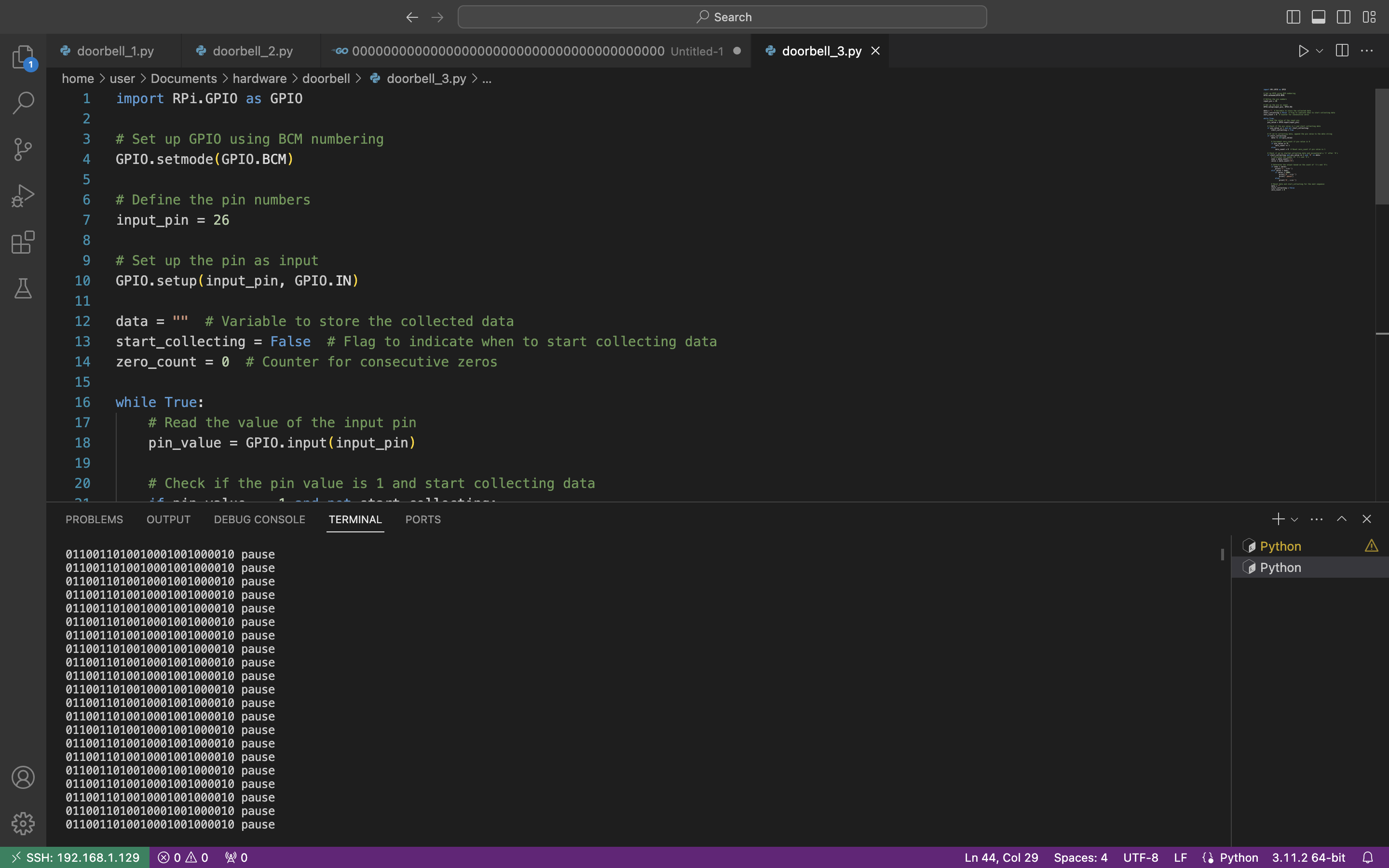
First, instead of “1s” and “0s” we can emulate the oscillograph and represent it in the graphical mode. Let’s substitute “1” as “|‾‾‾|_” and “0” as “|‾|___” and launch the code.
Ahhah, not the best representation, but we tried to do our best 🙂
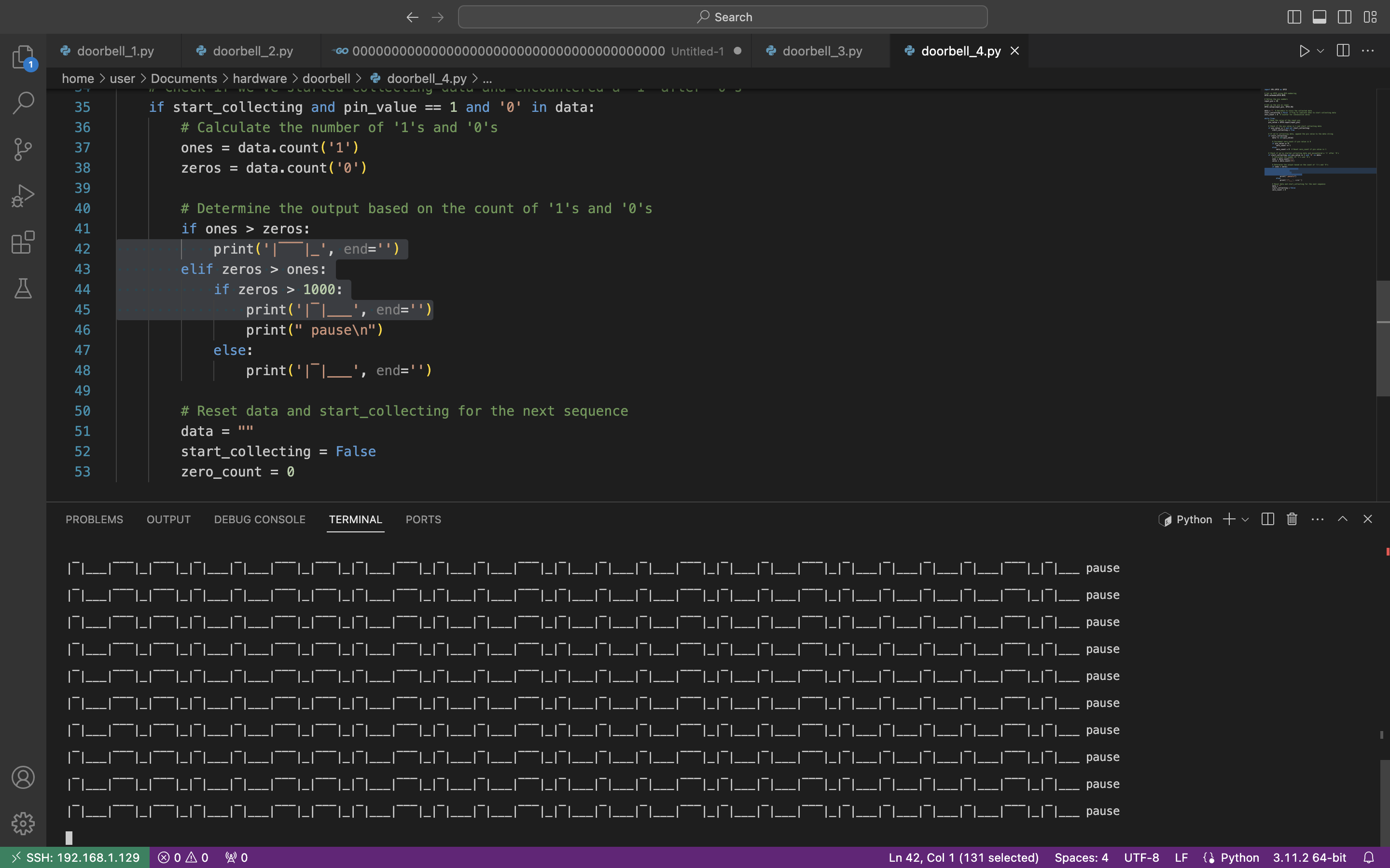
Second, we want to add additional information to our output, like the number of outputs / digits in our payload, it’s duration as well as the whole payload duration.
Also, the crucial one, we have to calculate the last digit correctly. In our previous code the last digit will be always 0 because we are comparing 1000 “zeros” with some “1s”. In the updated code we will get the average number of elements in items and decrease the number of “1s” to get the number of “0s”. And only after that compare them and get the correct last digit in the payload.
The final code is the next:
#Add number of outputs, duration of each element, payload duration and correct last digit
import RPi.GPIO as GPIO
import time
# Set up GPIO using BCM numbering
GPIO.setmode(GPIO.BCM)
# Define the pin numbers
input_pin = 26
# Set up the pin as input
GPIO.setup(input_pin, GPIO.IN)
data = “” # Variable to store the collected data
start_collecting = False # Flag to indicate when to start collecting data
zero_count = 0 # Counter for consecutive zeros
output_count = 0 # Counter for number of outputs
duration = 0 # Define the duration time
average10 = 0 # Counter of average digits
sum10 = 0 # Counter of each number of digits
while True:
# Read the value of the input pin
pin_value = GPIO.input(input_pin)
# Check if the pin value is 1 and start collecting data
if pin_value == 1 and not start_collecting:
start_collecting = True
# Record the start time of data collection
start_time = time.time()
# If we’re collecting data, append the pin value to the data string
if start_collecting:
data += str(pin_value)
# Increment zero_count if pin value is 0
if pin_value == 0:
zero_count += 1
else:
zero_count = 0 # Reset zero_count if pin value is 1
# Check if we’ve started collecting data and encountered a ‘1’ after ‘0’s
if start_collecting and pin_value == 1 and ‘0’ in data:
# Calculate the number of ‘1’s and ‘0’s
ones = data.count(‘1’)
zeros = data.count(‘0’)
sum10 += ones + zeros
# Determine the output based on the count of ‘1’s and ‘0’s
if ones > zeros:
print(‘1’, end=”)
output_count += 1
average10 = sum10 / output_count
elif zeros > ones:
if zeros > 1000:
output_count += 1
average10 = sum10 / output_count
# Calculating last element
last_zeros = average10 – ones
if last_zeros > ones:
print(‘0’, end=”)
else:
print(‘1’, end=”)
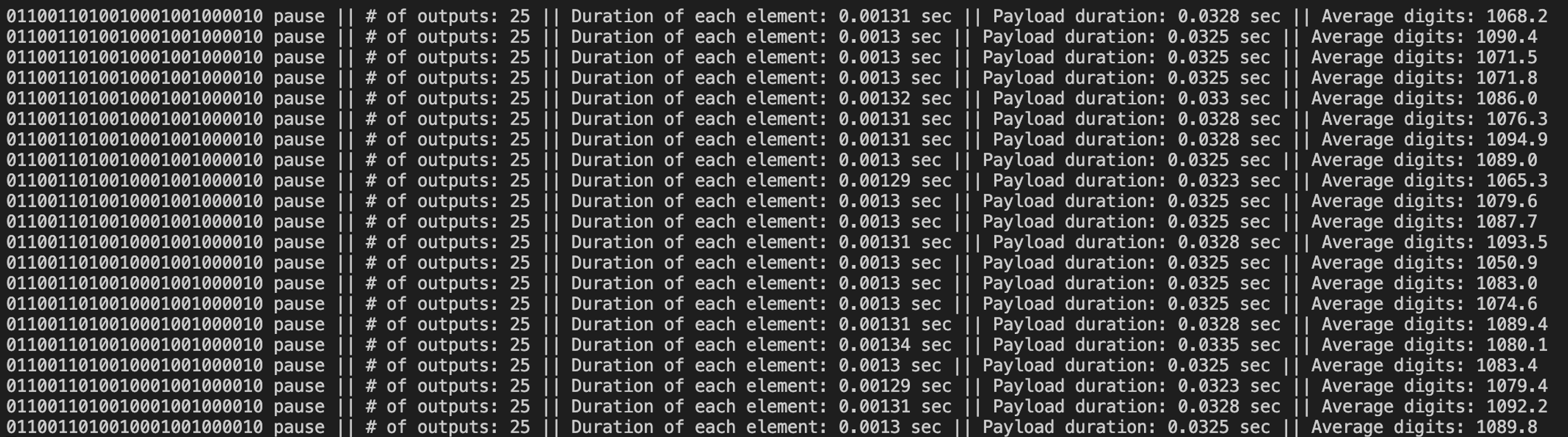
print(” pause || # of outputs:”, output_count, “|| Duration of each element:”, round(duration, 5), “sec || Payload duration:”, round(output_count * round(duration, 5),4), “sec || Average digits:”, round(average10,1))
output_count = 0
average10 = 0
sum10 = 0
else:
print(‘0’, end=”)
output_count += 1
average10 = sum10 / output_count
# Reset data and start_collecting for the next sequence
data = “”
start_collecting = False
# Record the end time of data collection
end_time = time.time()
# Calculate the duration of data collection
duration = end_time – start_time
zero_count = 0
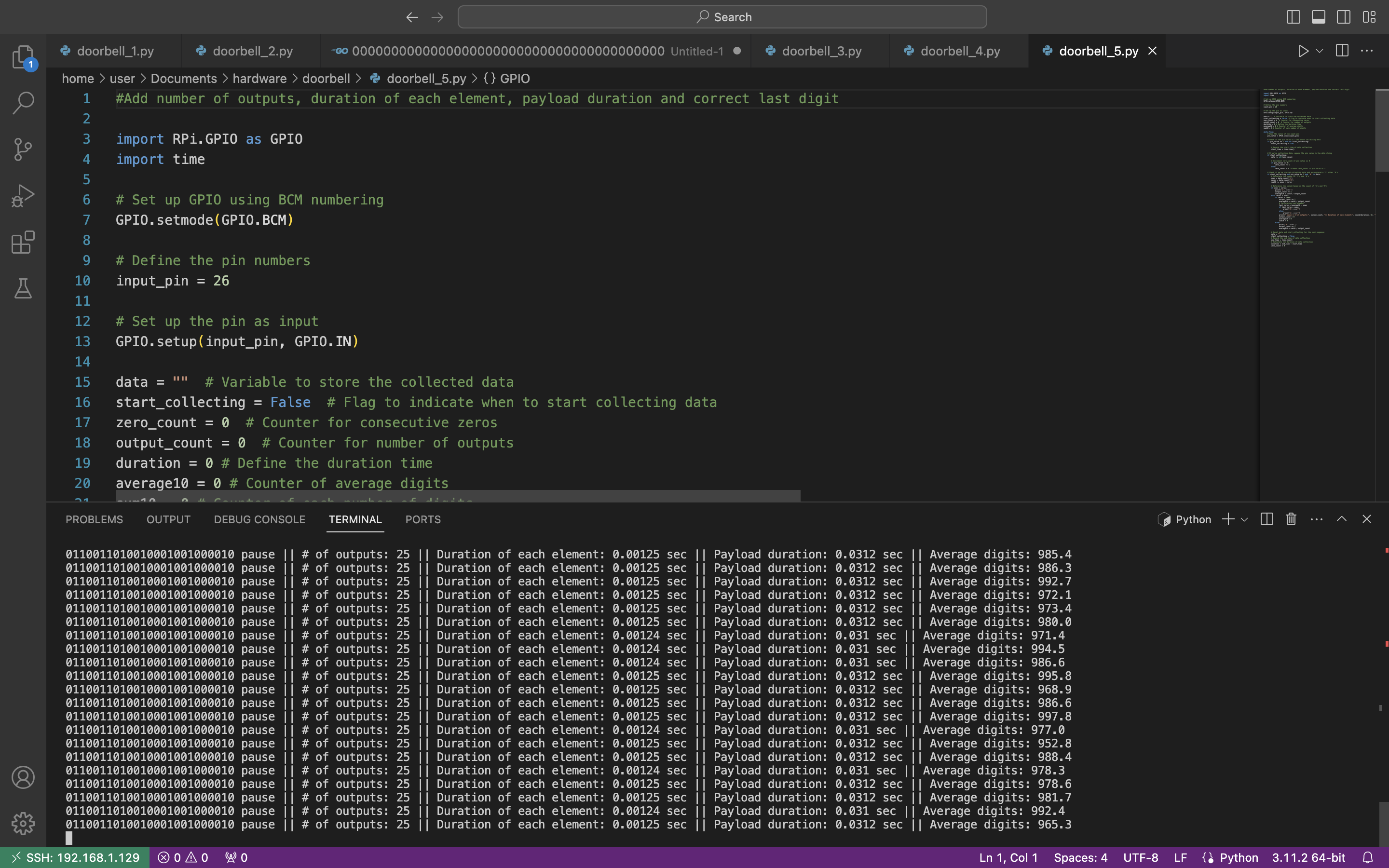
The average output is “0110011010010001001000010 pause || # of outputs: 25 || Duration of each element: 0.00125 sec || Payload duration: 0.0312 sec || Average digits: 997,0”.
Now, let’s compare that data with the radio wave:
- Duration of each element: 1,28 ms = 0,00128 sec (against 0.00125 sec)
- Average digits per element: 1285 (against 997).
As we can see, numbers are almost identical. We may try to explain that slight difference by many reasons like voltage, cables and connection quality, etc.
For instance, if we connect the remote to 3,3V (Pin # 1) instead of 5V (Pin # 4), the output is the next:
6. Afterword
Hardware hacking is definitely another level of hacking as it’s not only required the PC with open-source applications and programming language knowledge, but additional equipment, understanding how the electronic works and, the main one, be brave enough to risk your own stuff not being burn down 😉
But once you try it – it will be love at first sign. Don’t limit yourself, explore the hacking world.